DC Rowhouse Renovation - Rough Framing: the building takes shape by Gregory Upwall

The first shipment of framing lumber and plywood is delivered

The day that the old roof came off

The new upper 3rd story addition taking shape

View of 3rd-story addition from the front

The new rear additions taking shape at the 1st and second stories

Interior walls framed within the new 3rd-story addition

The additions framing nearly complete

View of 3rd-story addition from the front (the addition is barely visible above the original architectural rooftop features)

During the early portions of a renovation project patience and a good dose of faith are sometimes required since progress often seems slow and is less evident to the observer. But things finally seem to speed up once the portion of the construction referred to as “rough framing” begins. Why do we refer to this phase as “rough” framing? The framing part is pretty obvious, we are building “framed” portions of the building envelope with wood studs, joists and rafters. The rough part is a reference in contrast to “finish” carpentry, which refers to the trim, moldings, cabinetry, etc. that will come later. The rough framing or rough carpentry is referred to as “rough” since it is the structural portion of the carpentry that can be left rough since it will eventually be covered up by other finish materials. The rough framing is a pretty exciting time since it is the portion of the project when things move quickly and when the shell of the building really takes shape. 

Here in the North America (mostly US and Canada), where commercial forests are relatively abundant and soft-wood lumber is plentiful and cheap (relatively speaking), wood framing is the most common type of construction for homes and smaller residential buildings. Wood framing is particularly well suited for building additions onto older masonry buildings since it is relatively lightweight, yet strong and ductile, and also creates cavities that can be insulated within the walls and roof assemblies. Wood framing is also notable in it’s adaptability. Since wood members are cut and fastened together on site with relatively simple hand-held tools, it lends itself to creating custom sizes and configurations for walls, roofs and window openings.

With the newly framed rear and upper level building additions in place the size of our project has significantly grown in area, especially when viewed from the rear (something the neighbors have certainly noticed). With this project we are pleased with the resulting proportions and sight lines. In fact, due to the set-back of the new upper addition from the front wall of the original building, the upper-story addition is not even visible from the sidewalk in front of the house, and just barely visible when viewed from across the street. The volumes of the rear additions were designed to step in and out with balconies and are topped with an overhanging roof. The result is that the building feels less bulky when viewed in context with the neighboring houses.

 We have designed several projects that included either “pop-up” and “pop-back” type additions here in DC. These types of additions are somewhat controversial since many examples lack proper consideration to proportion and detail, and are often built in the place of traditional architectural features that have been removed. As we described in our earlier post “Design Approach” from August 10, we worked to place the volumes of the additions for this project in ways that fit within the new restrictions of the 2016 Zoning Regulations and within our own design criteria of hoping to conceal the additions. Based on the early glimpses of the framed building additions, we feel confident that our design objectives for the building additions -  that they are visually and proportionally complimentary to the original row-house – should prove to be successful. Now that the framing of the building envelope is complete, the next objective will be to get the exterior doors and windows installed, the roofing membranes installed and the building wrapped with a weather-resistant barrier so that we can keep the moisture from entering the inside of the house. At that point the house can be considered dry on the inside and we can actually start turning our focus to the interior finishes.

Sustainability Matters: Air Barriers by Gregory Upwall

On September the 26th, UDC hosted a Green Building seminar on air barriers. This was the last in a series of seminars organized by DCRA. If you are interested in attending any, they will resume in the spring of 2019. These seminars are free and open to the public so they are usually well attended and presented by people who are passionate about their subject.

Air barriers are defined as a “material or materials assembled and joined together to provide a barrier to air leakage through the building envelope. An air barrier may be a single material or a combination of materials”.

Air barriers stop the uncontrolled flow of air through a building’s exterior envelope. Airflow is caused by air moving from high pressure to low pressure. This moving air carries both heat and moisture. It can carry 50 to 100 times more moisture than diffusion alone. This is a huge consideration in a climate zone with high humidity such as ours; here in DC an air barrier becomes an even more essential component of any wall assembly.

Air leakage through a building’s envelope (walls, slab and roof) is generally caused by one of the following three phenomena:

a) Wind – on the exterior of a building creates positive pressure on the windward side and negative pressure on the leeward side which draws air through the building.

b) Stack Effect – warm air rises and cool air sinks.

c) Mechanical Pressurecaused by supply and exhaust imbalances.

We’ve all had the experience of standing beside a window and feeling cold. This is a common air barrier failure, and is an example of infiltration which is often caused by poorly sealed joints between adjacent building components. An example of exfiltration happens when a positively pressurized building has holes in the wall assembly. The pressure forces warm air through the insulation and into the wall cavity which cools causing condensation within the wall cavity.

High pitched roofs allow for passive ventilation (through the stack effect). Attic vents, dormer windows, vented soffits create heat differentials that allow for warm, moisture-laden air to rise and exit the building and cool air to enter.

Historically, buildings were not constructed to be airtight. They were drafty and poorly insulated but that also meant they had a lot of drying potential. But construction has changed, moving from masonry walls to the modern cavity wall. Interior finishes became more sensitive to relative humidity, residential HVAC proliferated increasing the need for more airtight homes. In response, the International Residential Code (IRC) adopted requirements for a continuous vapor barrier in 2009 following the International Building Code’s 2006 requirement.

In traditional masonry buildings, the air barrier is the wall itself. The thickness of the brick, paint on plaster, taped drywall or just paint on a brick wall all act as air barriers. Still, air leakage is quite common in these buildings. It is very difficult to make these layers continuous around the entire perimeter of the building envelope. When retrofitting older masonry buildings a lot of extra attention and detailing are required to eliminate gaps or leaks within the air barrier.

With the addition of air barriers, vapor barriers and proper thermal insulation, it becomes very important to take into account the unique hydrothermal properties of masonry walls. Misapplications can result in harmful effects like spalling since brick is designed to dry to both sides. Also the historical character of the building or neighborhood should be taken into consideration in any retrofit of a masonry building since it could result in changes to the exterior of the building.

The most important thing to remember about air barriers is continuity! A simple rule of thumb is on a drawing you should be able to put your finger on the air barrier and trace it around the entirety of the building perimeter without picking your finger up.

 Air barrier products may take several forms:

Mechanically-attached membranes (also known as housewraps),


self adhered membranes (peel and stick).

fluid applied membranes

and spray applied foam.

and spray applied foam.

There are several methods that are commonly used to measure the air-tightness of houses and buildings today. Blower door tests are used to help identify problem areas. A blower door is a powerful fan that mounts into the frame of an exterior door. The fan pulls air out of the house, lowering the air pressure inside. The higher outside air pressure then flows in through all unsealed cracks and openings. These tests determine the air infiltration rate of a building.

Blower Door Test

Thermal Imaging

Infra-red cameras can give real-time thermal images of the whole or parts of your home. When the blower door test is paired with a thermographic inspection, they can show exactly where cold air is flowing into your home. These tests must performed by professional energy auditors. It is important to employ these measures intermittently during the construction process since these tools are the best way to determine whether the assemblies are air-tight. They need to be carried out during construction while the building envelope components are still accessible (so that problem areas/leaks can be identified and fixed).

If you are renovating, building an addition to your existing house, or building from the ground up, you should familiarize yourself with Table 402.4.1.1 in the International Energy Code(IECC). In DC the Green Building reviewers at DCRA will check to make sure that this table and the components of the air barrier are properly identified in the drawings when a building permit is under review.

Air sealing also makes a big difference to indoor comfort. If you have an older leaky home and don’t want to spend the money on expensive retrofits you might want to spend some time on simple air-sealing efforts like caulking around window frame perimeters and electrical outlets and checking wall/ceiling joints for leaks. Ensuring that windows properly lock and seal and adding door sweeps also make a big difference. Weather-stripping, the process of sealing around doors, and windows, is another simple and cheap way to mitigate leakage without breaking the bank.

In single family homes, leakage areas are typically found in these areas:

·       Recessed lights

·       Duct connections

·       Attic connection between top-plate and drywall in the interior of building.

·       Corners

·       Rim joists

·       Attic Hatches

·       Chimneys (without dampers)

·       Poorly built additions

·       Ill-fitting door and window frames (in older homes)

With an airtight house you will have lower heating bills, fewer drafts (i.e. more comfort), reduced chance of mold and rot because of moisture, and a better performing ventilation system. Now that’s a wrap!

DC Rowhouse Renovation - Rebuilding the Old Garage with Masonry & Steel by Gregory Upwall

View from the rear of the old garage when we purchased the house

When we purchased the house the one-car garage attached to the back was perhaps the scariest part. The side wall was severely sagging inward and the steel beam supporting the roof looked like it consisted of more rust than actual steel – both looked ready to collapse at any moment. Suffice to say that we felt no hesitation about tearing it down, and of course, we decided to re-build it stronger and better than before.

The masonry that we chose is a special “ground-face” CMU (aka: concrete masonry unit). A quick aside on CMU: most people call this material “cinder block” and think of it as common and ugly. We admit that the standard product that is used most commonly is not much to write home about. But the ground-face block is a whole different breed. First off, the cement and aggregates come in a range of colors (we chose a slate grey). And secondly, after the exterior faces have been ground smooth in the factory, this block is smooth to the touch and has the appearance similar to terrazzo. (We really like the product and hate it when people write it off as just cinder block…).

As was mentioned in our post about foundations (see Strengthening the original: part 1) we installed new reinforced concrete foundations around the perimeter of the garage. From the foundations vertical reinforcing bars (re-bar) were extended vertically up from the foundation so that as the block wall is built with the bars extending up through the hollow cells in the center of the blocks. As the block is laid the cells are filled with a solid grout mixture that encases the re-bar. Once the walls have fully dried they form a continuous structure from the foundation to the top, tied together by the steel reinforcing bars.

The roof of the new garage was another design challenge since it will also support the small walk-out deck off the kitchen at the main floor level above. We spent extra time detailing the construction of the garage roof to allow for it to step down from the interior floor level and still leave room for the decking boards. With this detail, the finished decking will be flush with the interior floor and the water-proofing below the decking will be concealed from view. To achieve stepped-down area on below the decking we needed to come up with the thinnest possible roof structure over the garage since we could not afford to sacrifice ceiling clearance in the garage below (otherwise there would not be enough ceiling clearance for my beloved 1990 VW Westfalia Vanagon).

After considering several options, we chose small 4” deep steel wide flange beams. These compact beams are very strong compared to wood framing and will provide the needed support for the decking above. Our contractor cut slots in the top of the masonry wall to set each beam into, then grouted them in place. Once the wood blocking was in place and fastened into the sides of the masonry wall the plywood sheathing was fastened to the blocking to create a rigid surface that ends up stabilizing the tops of the walls and tying them together into one cohesive structure.

view of the CMU blocks being set on the foundation with the steel reinforcing bars extending up through the hollow cells

View of the masonry walls under construction

View showing step-down in the floor over the garage that will allow for waterproofing to be concealed and deck boards to bet set flush with the floor inside

view from above showing the CMU block on palettes and the top of the foundation wall with the vertical reinforcing bars ready to set the masonry onto

view showing the this steel beams with the roof decking installed. The overall depth of the beams & decking is only 4.5”!

Section drawing through garage showing step-down in floor above garage and custom roll-up door at garage opening

For the back of the garage we will have a custom roll-up metal door fabricated and installed that will yield the maximum clear opening width and height for the garage door opening when fully opened. In order to maximize the vertical clearance at the garage door opening, we have decided to mount the coil for the rolling door above the garage mounted to steel posts. At the completion of the project we plan to build low cedar walls around the perimeter of the deck that will conceal the roll-up door housing.

Wall Section through custom roll-up door at garage opening

These details are all custom and require special attention, but they are necessary when building within a tight confined area such as this house. We feel confident that they will seem well worth all the effort once the project is complete.

DC Rowhouse Renovation - Strengthening the Original - Part 2: Floor Framing by Gregory Upwall

While the steel fabrication crew was busy installing the steel frame, our general contractor was able to work on reframing the existing floors. This is the other major type of re-strengthening work on a renovation project like ours. With the removal of the old interior walls, the original floor joists are effectively left unsupported in the middle and the distance that they “span” is now the full width of the house. Also as part of our new design, the stairway is being relocated from it’s original location to a new location along the alley side wall at the rear of the house. In order to move the stairway an entirely new opening in each floor has to be created for the stairway to fit into. All of this reframing was installed in accordance with the structural engineer’s framing plans and details.

In areas where the span distance of the original floor joists has been increased by the removal of interior walls the structural engineer has called for new wood floor joists to be “sistered” along the side of each existing joist. Sistering is a term that refers to connecting a new joist into the old joist by installing equally spaced screws through the side of the new joist into the existing joist for the entire length of the span. With the new joist “sistered” to the old the two effectively act as one stronger joist.

In certain locations (such as the perimeter of the floor openings for the new stairway) stronger wood beams are needed to carry the larger concentrated loads that occur from attaching the stairway and the adjacent floor areas. In these locations engineered lumber is typically used instead of standard framing lumber since it is stronger. The term engineered lumber is used to describe a variety of different products, but all engineered lumber products are made from wood fibers, veneers, or layers that are bonded together with adhesives in a factory. While the manufacturing of engineered lumber does come with a variety of factors that can increase it’s overall sustainability as a building product, a major advantage comes from the fact that engineered wood does not require the harvesting of large mature trees since the wood fibers used in it’s production are generally from smaller and younger trees. is For our project the engineer called for “LVL” beams (LVL stands for laminated veneer lumber) in these locations.

Removing a section of the old subfloor to create a space for installing the new beam in the floor framing

Measuring the opening for the new stairway opening

Lifting the new beam into place

Setting the new beam into place

The new beams forming the opening for the new stairway

Our framing crew had to remove sections of the old floor framing and cut “pockets” into the old masonry walls in order to insert the new beams. Once all of the new joists and beams were installed the original subfloor boards were removed and a new layer of “Advantech” floor sheathing was installed. Advantech is a great new plywood flooring and wall sheathing product that has greater moisture resistance, stiffness and fastener holding characteristics than typical plywood. The Advantech sheathing also has a “tongue & groove” profile along the edges of the panels allowing them to interlock for greater strength.

Now that all of the interior floor levels have been re-framed our contractor can turn their attention to re-building the garage at the rear of the house. Once the new garage is in place they will be able to start framing the new rear walls and then the new addition at the top of the house – very exciting!

A view of the newly re-framed upper floors (looking up from the 1st floor)

Floor framing and steel posts in place

A view below the 1st floor showing the new LVL beams, Advantech sheathing, and the new steel posts place

View from rear alley with scaffolding removed showing steel frame in place and new floor framing in progress

Sustainability Matters: Achieving Net Zero Energy Buildings by Gregory Upwall

On September 5th 2018 we attended the “Achieving Net-Zero Energy Buildings Workshop” organized by the New Building Institute (NBI) in collaboration with two DC Government agencies: DCRA & DOEE. The conference was held at The University of The District of Columbia’s impressive new student center and was very well attended. The conference started by emphasizing several troubling statistics to those of us in attendance as a reminder of why this topic is so important:

·       74% of carbon emissions come from buildings,

·       While the US comprises only 4% of the world’s population, we produce 15% of all greenhouse gas emissions.

Washington DC, the city we call home, has striven to be a leader in sustainability. In 2017, DC was named the first LEED Platinum city in the world. In this spirit, DC has committed to becoming a carbon neutral city by 2050. The built environment will play a critical role in mitigating the effects of climate change. Tommy Wells, the director of DOEE, opened the workshop by saying, “We don’t tear down a lot of buildings in DC. So new buildings must be rock-stars, and we need to learn how to retrofit the existing stock” in order to address global warming, climate change and issues of resilience.

So what is net zero, you might ask? The Net Zero Energy or Zero Net Energy building (ZNE) is defined as:  an energy-efficient building that produces at least as much energy as it uses in a year, when grid-supplied energy is accounted for at the source (including primary energy for generation, transmission and delivery to the site).

A study conducted a decade ago revealed that NZE buildings were possible in every climate zone in the US, and today there are many are examples across the country.

 Schools are currently the most common NZE buildings by type, followed by offices and multifamily construction.

 The main benefits of these hyper efficient building are: reduced greenhouse emissions, increased productivity and well-being of occupants, and Savings (Utility bills).


American Geophysical Union Building in Washington DC

 One of the case-studies presented at the workshop was The American Geophysical Union building, currently under construction right here in DC (200 Florida Ave, NW). This is a conversion of an old building into an exemplar of energy efficiency and modern amenities. The new facility will boast a solar array, a roof garden, a green wall that runs the height of the interior space, dynamic glass shading, radiant cooling ceiling panels and a sewer heat exchange to name a few. The USGBC will be holding tours of the building on October 24th so sign up!

 If you happen to be in Virginia, you might want to visit one of VMDO Architects’ pioneering high-performing projects. They gave a presentation on their award-winning net zero elementary school, Discovery Elementary, a recently completed in Arlington, Virginia.


Discovery Elementary School

For more examples, NBI has a database of North America’s most advanced energy efficiency commercial projects including zero and ultra-low energy projects.

So what goes into achieving a net zero building? All the presenters at the conference stressed the importance of engaging stakeholders and setting target performance metrics early in the design process (and to define them in the RFP). Once the design team is put together and everybody is on board, owners, occupants, and the design team members should come together to brainstorm potential strategies and technologies in what are called Integrated design Charettes. Iterative energy modeling is critical for hitting those targets. Monitoring building and occupant patterns will ensure that you not only design to net-zero but that your building actually performs at net-zero.

 In an effort to be sustainability leader, DC has set some ambitious goals for the future of our city. Clean Energy DC is DC’s Climate Mitigation Plan. It includes DOEE’s Sustainable DC 2032 climate and energy targets. By 2032 all new construction in DC will be (required to be?) Net Zero. Greenhouse gas emissions will be reduced by 100% by 2050. DOEE’s 50/50/50 challenge seeks to cut energy use by 50%, increase the use of renewables by 50% and reduce greenhouse gas emissions by 50%. DCRA will be adopting codes that mandate new residential construction to be net zero by 2020 and new commercial construction by 2026.  They also announced that in the coming months they will be introducing “Appendix Z” – an incentivized, voluntary net zero building program for residential and commercial buildings. These objectives together are conceived of as a grass roots effort, driven by the community to encourage early adopters to lead the way and prime the industry for the city’s net-zero goals. 

 For more information or technical and financial support, the DC government encourages residents to refer to the following resources:

DC Pace

DC Green Bank

Solar For All

DC Rowhouse Renovation - Strengthening the Original - Part 1: Foundations and Structural Bracing by Gregory Upwall

To determine the depth and size of the existing foundations test pits were dug.

Now that the demolition work is done, we have reached the point in the project where the new construction can begin - and the new work starts with the foundations. To most eyes, the foundation work can seem to move very slowly and the improvements can seem somewhat imperceptible and/or unremarkable. But to be sure, this phase is probably more important than any that will follow.

The depth and size of the existing footings are critical information for the structural engineer in determining whether new foundation work will be required to accommodate the new portions of the project.

If the foundation work is inadequate, the building could settle or shift, causing cracks and structural issues in the rest of the house. At the time that this house was built (nearly 100 years ago) the importance of the foundation work was not fully understood as it is understood today. Although the craftsman who originally built these houses were very skilled in the arts of masonry and carpentry, the foundations that they placed the buildings on were often inadequate compared to today’s standards. Fortunately, there has been much progress over the years in understanding the importance of well-constructed foundations. Foundations are to buildings what roots are to trees, they are the un-sung heroes of all good construction. For without them, the parts of the building that we see and occupy would be greatly compromised.

Remember that our project falls under what we would consider an “intensive renovation”, meaning that our goal is to replace and upgrade as many of the components and systems (to meet modern standards) as possible while retaining the original exterior walls and architectural features of the house. Since we have removed the entire rear wall of the original house to make way for the new expansion of the house, our structural engineer determined that most of the new fortifications were required in that area of the house.

Our foundation work was started by documenting the size and condition of the original foundations below the existing house. In order to see and measure the original foundations test pits were dug during the demolition phase and a soils report was prepared by a geotechnical consultant following the directives of our structural engineer’s drawings and specifications. Many readers of this blog may have heard of “under-pinning”, which is a term that is commonly used to describe the process of excavating below existing foundations in order to install new reinforced concrete foundations below them. This is usually done in order to create higher ceilings in low basement or crawlspace areas. This work can be very slow and expensive since the new foundations have to be installed in short segments, one section at a time. Thankfully in our case, since the existing foundations were low enough, we were able to lower the basement slab by a few inches without triggering under-pinning on this project, which was a big cost savings!

Foundations require digging, and since we are building them under the existing house, most of the digging must be done by hand. Our contractor and his crew actually broke apart and removed the original concrete floor in the basement and several inches of the soil beneath. All of the debris was piled up in the basement and then hauled by hand out of the basement into a truck. This work is painstaking and we have a great appreciation for the workers who do this hard work.

Soil and concrete had to be dug by hand and piled within the basement before being hauled away.

This photo shows the large pit dug at the rear corner of the original house which extends completely underneath the original foundation.

Once the concrete was removed, large pits were dug at both rear corners of the house for the two new large foundations required in these locations. Since we had removed the old garage and will be rebuilding it entirely, a trench was dug around the entire perimeter of the garage for the new garage foundations. The other places where new foundations were required are at several interior posts that will support the new stairway, and below the new/re-built rear wall of the house. Reinforcing steel bars (or “re-bar”) were laid in the holes and extended vertically prior to pouring concrete. After the concrete is poured, it “cures” over the next several weeks before reaching full-strength. 

Pits dug for new footings that will support the new stairway on the interior of the house.

New trench for Garage foundations (ready for concrete to be poured).


Structural engineer’s drawing showing new foundation and steel frame.

Trench for the new garage foundation wall ready for concrete to be poured (with steel re-bar installed).


New steel frame installed at basement level. The bolts have been set into the old brick wall with epoxy to create a stronger bond with the old brick.

Since the rear wall and portions of the floors were removed for the new stairway, the existing alley side wall was left unstable from the engineer’s point of view, so a structural steel frame was required in order to stabilize the wall and to stiffen the house against lateral forces (such as wind and seismic forces). Since the side wall faces the alley and is not against another rowhouse, it has increased bracing requirements which in this case were addressed by the internal steel frame. The steel frame was erected on site by a steel fabrication contractor and was fastened to the brick by a series of bolts that were drilled into the brick and set with epoxy to help them bond with the old brick. The steel frame has been designed to fit along the interior side of the brick and will actually be concealed behind the drywall once the project is finished. With the foundations and the steel frame in place the we can now turn our attention to the wood framing. The next step is reconstructing the existing floors to strengthen them and to create the opening for the new stairway……

View of new internal steel frame (looking down from 1st floor)

View of new internal steel frame (looking from rear yard)

View from rear alley showing scaffolding during installation of steel frame.

Steel fabrication contractor on site installing steel frame.

Steel fabrication contractor on site installing steel frame.

Steel fabrication contractor on site installing steel frame.

DC Rowhouse Renovation - The Demolition Phase by Gregory Upwall

View of interior after removal of walls and finishes

View of interior after removal of walls and finishes

The first phase of any renovation project is demolition, or more accurately, “selective demolition”. We typically prepare specific demolition drawings which indicate specific parts of the building to be removed in order to accommodate the new design. The removed components usually include walls, roofs, floors (or portions of them), windows, doors, cabinetry, plumbing fixtures, etc. For this project the demolition was significant. In order to accommodate the new rear addition, all 3 stories of the original rear brick wall had to be completely removed. To make way for the new 3rdfloor addition, the original roof will be removed entirely. On the interior all of the original walls, cabinetry, radiators, plumbing, electrical wiring and fixtures were completely removed. Even the original stairways were removed since they will be in a different location in the new design – this is what is typically referred to as “gutting” the house.

2nd floor after interior demolition

2nd floor after interior demolition

2nd floor after interior demolition

2nd floor after interior demolition

While the housing stock here in DC spans several centuries, the majority that come into our office as renovation projects were built between 1890-1930. Homes of this era can often contain old layers of lead paint and asbestos (which was used widely in many different building products from flooring to insulation to siding). These materials are hazardous and should be removed by professional abatement contractors who are trained in the proper removal and disposal of these materials. Another common concern comes from the very dust that is produced when removing old building materials since it commonly contains significant amounts of mold and other contaminants that can cause respiratory problems. These materials and conditions should not be overlooked and proper measures should be taken during the removal and disposal of materials that are to be removed from the building.

Another consideration that we recommend to our clients during the demolition phase of the project is the opportunity to salvage certain materials that are being removed for re-use or recycling. This is commonly referred to as “de-construction” and can help to divert significant amounts of waste from ending up in the landfill. It is generally advisable to consult with a de-construction contractor prior to the start of demolition work in order to identify which materials, if any, are candidates for salvage. In most municipalities today construction waste is required to be sorted and hauled to different facilities. Metals such as copper and steel are good candidates for recycling. The goals should always be to a.) dispose of all materials properly, b.) salvage or donate any worthy materials for re-use, and c.) minimize the volume of material that will end up in the landfill.

Another concept that is worth mentioning whenever we discuss demolition is that of temporary “shoring”. This refers to any temporary measures or construction that will be required to support the building in the time between the removal of the existing components until the installation of the new structural components. Shoring often includes temporary posts and beams that must be securely installed by the contractor prior to removing portions of the existing building. In this project since so many walls are being removed and new openings are being created within the walls and floors (for new windows and stairways accordingly) it was necessary to install a temporary bearing wall at the basement and 1stfloor levels in order to support the existing floor framing during construction.

View of original stairway (before it was removed)

View of original stairway (before it was removed)

Demolition often goes quickly once started so this is often a time when it appears that a lot of progress is being made, which can be very satisfying (especially after months of waiting for permits to be approved). It can be both scary and deeply satisfying to see the old, worn and dilapidated parts of the building being removed to make way for the new construction to come. This is also the phase when you get to see the real “bones” of the building and to identify areas in need of repair. This is generally the time when we remind ourselves of the common saying  that “it’s going to get worse before it gets better”.

DC Rowhouse Renovation - Pre-Construction Challenges by Gregory Upwall

The Challenges: Permitting, Contractors, Budget:

This project, like so many that we undertake for our clients, faced a list of challenges in the DCRA permit review process. DCRA’s permit reviews have gotten increasingly more focused over the past several years, but we have been actively following and keeping pace with their increased efforts. A single-family house renovation and addition such as this one is reviewed by as many as 8-10 separate review disciplines, each with their own comments and requirements. But finally, after multiple rounds of comments and 8 months of review, we were granted our building permit and allowed to start construction. Keep in mind that while the proposed drawings were under review at DCRA, we had gone ahead and pulled a separate demolition permit that allowed us to remove all of the interior (non load-bearing) walls and finishes (we highly recommend this to all of our clients when possible as it allows everyone to see the actual structural members). During this time we also had exploratory test pits dug at the corners in the existing basement to determine the depth, size and soil conditions of the existing footings (aka “footers”). This information along with a simple soil bearing report (prepared by a licensed geo-technical engineer) allowed our structural engineer to determine how much the basement slab could be lowered along with sizing any new foundation work needed to support our new design.

A sheet from the Construction Drawing Set

A sheet from the Construction Drawing Set

Our budget for the renovations is roughly $250,000 which also creates a challenge for such an extensive renovation in today’s DC construction market. In an effort to try to stay within this budget we decided to work directly with each of the individual sub-contractors rather than hiring a general contractor to manage all of the various components of the project. Since we have worked closely with many different contractors we were able to find a team of subs all with competitive prices and whom we think will do a good job on the project. This approach where the architect becomes involved in the day-to-day oversight and management, more commonly referred to as a “Design-Build” approach, also allows us to modify and adapt the design and details along the way in response to unforeseen flaws within the existing building and in response to budget concerns. This design-build process also allows us to become intimately familiar with all of the details and particulars of the project. It’s very exciting for us as architects to be allowed to become so involved with the construction process.

DC Rowhouse Renovation - Design Approach by Gregory Upwall

Design, Space Constraints, Goals

The proposed design, retains the original front facade.

This old rowhouse, like so many that our clients come to us with, was compartmentalized into small cramped rooms and was lacking for natural light in the interior. (It was what they call a “Wardman style” here in DC – but in this case, a mini-Wardman.) (insert link about history of Wardman style) Since the house was so small (less than 400 square feet per floor on each of the existing three floors) we knew right away that an addition to the house ranked high on the wish list (see “Pop-ups” & “pop-backs” below). After a few months of exploring different design ideas, we arrived at a scheme that will add a new upper level 3rd story to the house along with some modest additions on the back of the existing house. The selected design aims to open up each floor of the house by removing many of the internal partition walls on the living levels and by creating an open stairway that will bring in daylight from a three-story glass block window that will be inset into the existing west-facing alley-side wall. Glass block is a good choice for this location due to it’s inherent durability, and its ability to buffer sound better than most window wall systems. We also liked glass block since it is still a masonry (modular) product and we felt it to be a more complementary material for creating a large glass opening in the 100+ year old wall.

Expanding the Envelope: “Pop-ups” & “pop-backs"

Proposed rear design showing new upper and rear addition.

As mentioned, this house was small – about 980 square feet total in 3 levels. If ever there was a time where a vertical addition (aka “pop-up”) or rear addition (“pop-back”) made sense, it was here. We have successfully designed several of these additions for other clients – and yes, we know that this is a touchy topic for some out there. Our feeling on the subject is that these additions are not, in and of themselves, either good or bad. There are well-designed additions – and well, those that should have never been allowed to be built. These additions should always be set back from the existing architectural features of the house, which should be preserved. When designed correctly, and in deference to the original façade and historical features of the house, these additions are an opportunity for great creativity and possibility in revitalizing old housing stock in a city faced with rising property values and a shortage of good quality housing. We also believe that the added density created by these additions is an important component of sustainable redevelopment. By adding square footage, bedrooms, or even additional living units to existing buildings we are doing so without putting a strain on new infrastructure (roads, utilities, services) that is typically associated with new housing developments. In fact, in our opinion, zoning regulations for cities like DC with so much existing single-family housing stock, should encourage this kind of increased density – the new DC 2016 Zoning Regulations landed somewhere in the middle on this topic (more on this in a later post). With well-designed additions to existing stock, we can create within our existing neighborhoods, more living space and more opportunities for families and individuals to live together within these revitalized neighborhoods.


DC Rowhouse Renovation - The Endeavor Begins... by Gregory Upwall

Project Introduction

Existing property at the time of purchase.

For those of us who choose to live in a rapidly gentrifying metropolitan region, the cost of housing and the dream of owning a home are usually near the top of the list of challenges that we live with. The desire to live in the urban center where walk-ability and proximity between home, work , and regular daily activities are a real possibility is a primary motivation for families to want to live in the urban center.

Washington DC is fast becoming a highly desirable city for people who are eager to ditch their cars, long daily commutes, traffic jams, etc. With so many neighborhoods experiencing this new wave of desirability and revitalization comes the less desirable realities: escalating costs, and a limited supply of homes that can’t keep up with the growing demand. Not to mention, you get less home for your dollar when you live in the city. Still, for those of us who dream of a simpler, more efficient, car-free lifestyle, the trade-offs are something we are willing to accept.

Many of our clients are recent buyers who, motivated by the above reasons, have decided to purchase a home in an up-and-coming neighborhood that is, well, what you might call a “fixer-upper”. In DC, that term can often be an understatement as many of the older row homes have been sorely neglected and are in need of serious upgrades both structurally and aesthetically.

A very typical category of our clientele are people who might have never envisioned themselves entering the home renovation arena, but who have found themselves there nonetheless, typically because the price of homes already renovated on the market have been too high for them to swallow or afford. And suddenly, along with their decision to acquire an old house, they have entered a world filled with uncertainties.

In November of 2017, I myself took the plunge and decided to buy a charming but long overdue in the need-for-upgrading rowhouse near Howard University in the Pleasant Plains neighborhood (roughly between Columbia Heights and Petworth). And now I, just like so many of our clients, have committed to the uncertain and financially precarious undertaking of a full and intensive renovation of the house.  This series of blog posts will document the project throughout the renovation both in photographs and words in the hope that it might shed some light on the various phases of the work and explore different aspects of the project as they come to life. It is our hope that by documenting this process we will be able to help those of you who might be considering taking on your own fixer-upper project.

Existing rear view of house (at time of purchase)

The Property

The house that I finally purchased (I had put in bids on two other DC rowhomes in the preceding two years – both of which were rejected) is a small Wardman style rowhouse (we’ll call it a “mini-Wardman”) located on a tree-lined one-way street with a great “neighborhoody” feel. The house is an end unit, meaning that its west wall faces directly onto an alley. This was seen as a major selling point since that alley wall meant additional opportunities to bring in natural daylight to the re-designed interiors (more on this later when we discuss Design). The house is two stories over a basement with very compact living, dining, and kitchen on the 1st floor, and two bedrooms + one bath on the 2nd floor. At the rear of the house is an attached 1-car garage. The woman that I bought the home from had lived in the house since 1960 and had not undertaken any remodeling or upgrades since then.


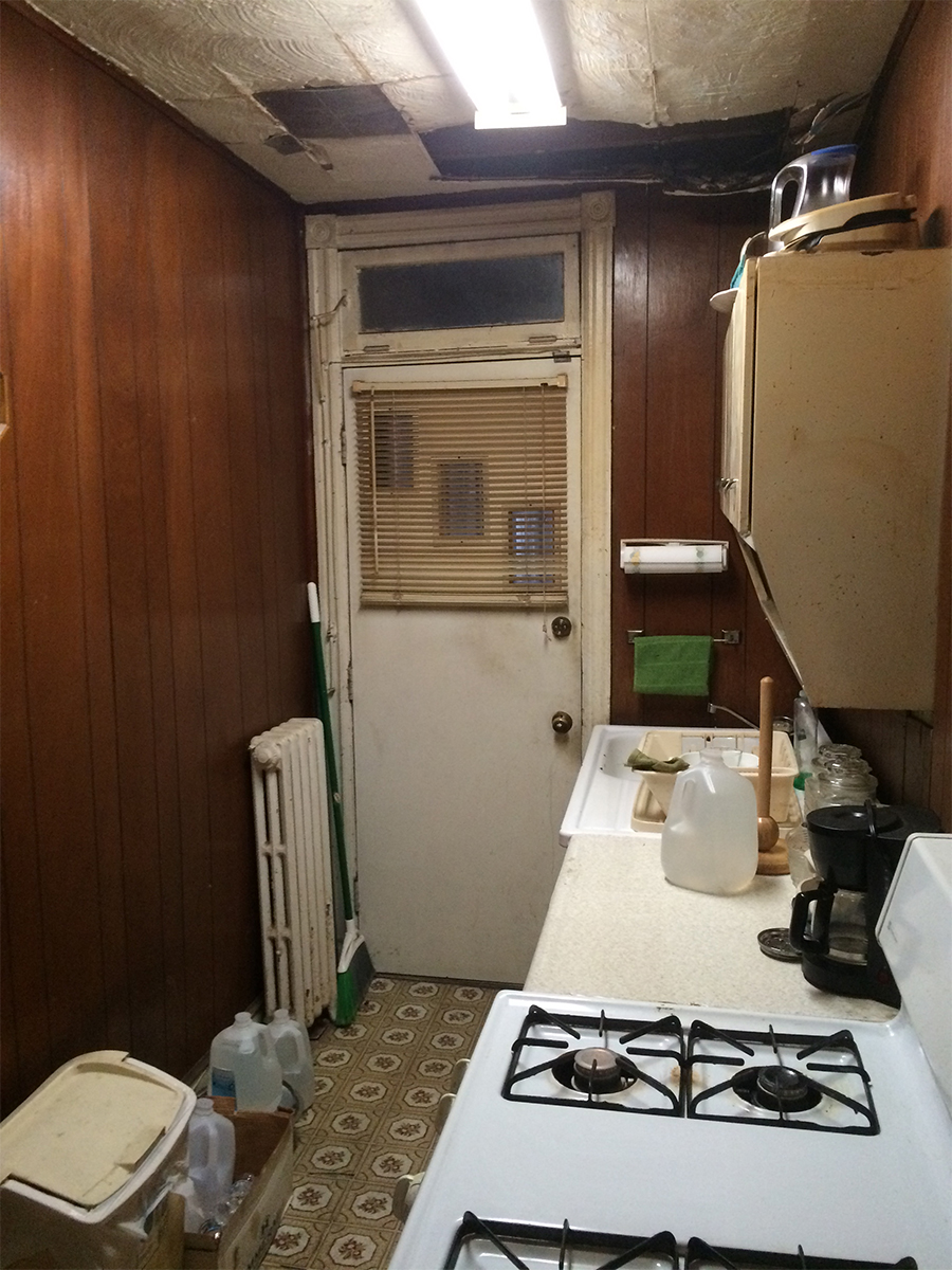
Existing kitchern at time of purchase

Existing kitchern at time of purchase